A creative furniture idea becomes manufacturable only when the design records dimensions, material behaviour, cutter access, assembly clearances and finishing requirements—not just an attractive 3D image. By following a controlled workflow, you can judge whether a concept is machinable, compare proposals accurately and approve files that are ready for production and installation.
Key takeaways
- Start with measured dimensions, materials, joints and installation constraints.
- Choose CAD and export formats that preserve geometry and manufacturing data.
- Check tool access, cutter diameter, material thickness and workholding before machining.
- Compare tolerances, toolpaths, finish quality, revisions and installation details before approval.
How does a furniture idea become a CNC-ready 3D model?
A CNC-ready 3D model begins with a measurable furniture design brief, not a reference image alone. The CNC 3D design workflow is:
1. Record site measurements, including opening width and height, walls, floors, obstructions and access routes.
2. Collect reference images and hand sketches showing the intended pattern, proportions, hardware, finish and viewing angle.
3. Before modelling, confirm panel thickness, material, grain direction, mounting method, edge clearances, pattern scale and intended viewing distance. These decisions affect strength, appearance and cutter access.
4. Build the design in parametric CAD furniture design software. Set bay width, panel thickness, connector spacing, handedness and replacement-part dimensions as controlled parameters, so one approved change updates related panels, holes and drawings.
5. Prepare toolpaths from the verified model, checking stock size, datum, cutter access, machining depth and holding points.
6. Cut a test piece to check fit, pattern scale, grain behaviour, edge clearance and finish allowance. A screen preview cannot reveal every assembly or cutting problem.
7. Machine the approved parts, label them against the drawings, then install them using the specified mounting method and site dimensions. A modular system built from separately edited parts can produce mismatched holes, reversed panels and replacement components that no longer fit.
Which digital format fits the furniture component?
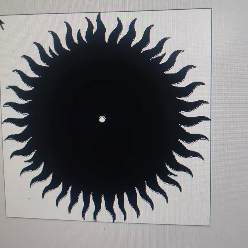
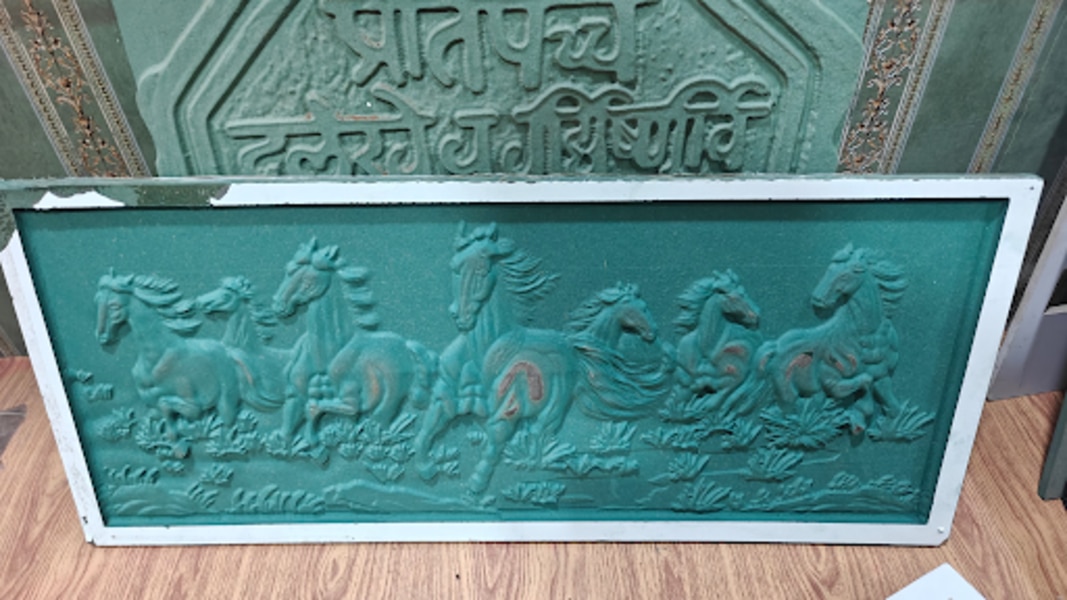
Choose the file that matches the cut. A 2D vector drawing in DXF or SVG suits flat profiles, jali openings and cut-through outlines. A 2.5D relief suits raised or recessed patterns with controlled depth. A complete 3D CAD model suits sculpted components and compound surfaces.
A shaded render communicates appearance only; the 3D render versus CNC model distinction matters because a render cannot drive machining by itself.
| Option | Accuracy and surface character | Speed, cost and suitable use |
|---|---|---|
| CNC 3D machining | Repeatable, with scallops from ball-nose passes | Slower and costlier; carved panels and sculpted parts |
| Hand carving | Individual tool marks and organic variation | Slow, labour-intensive; one-off artistic details |
| Laser cutting | Precise flat outlines with heat-darkened edges | Fast for thin sheets; jali and cut-through patterns |
| 3D printing | Layer lines and build-direction limits | Useful for prototypes and complex small parts |
| 2D CNC routing | Clean planar cuts, no true compound form | Efficient for profiles, joinery and flat panels |
A three-axis machine needs repositioning when the cutter cannot reach a face. Undercuts, enclosed cavities and compound curves may require special tooling, a fourth axis or a fifth axis; otherwise the design must be split into accessible parts. A smaller stepover reduces scallops but increases machining time.
How do you test whether the concept can actually be machined?
An attractive form is machinable only if its thin parts survive cutting and use. Set a minimum bridge width for each material and load, then inspect fragile projections, edge margins, relief depth and cutter access.
A 6 mm end mill leaves an internal corner radius of at least 3 mm; a square mortise therefore needs a dog-bone relief, T-bone relief, smaller cutter or redesigned joint.
- Keep narrow tabs, necks and projections aligned with the grain where possible; short grain can snap despite adequate model thickness.
- Leave enough edge margin for cutting and fasteners; a hole too close to an edge can split the part or blow out during routing.
- Check relief depth against remaining material, especially on thin panels and back-lit screens.
- Size joints from measured stock, not the label: nominal 18 mm MDF or plywood can differ in actual thickness, density and screw holding.
| Material | Thickness and edge strength | Grain, movement and fixing |
|---|---|---|
| MDF | Uniform thickness; weak exposed edges | No grain; low moisture stability; use inserts or knock-down fittings |
| Plywood | Check measured thickness; stronger edges | Alternating grain limits movement; good screw holding |
| Natural timber | Thickness varies; edges can be strong | Grain direction controls strength; allow cross-grain movement with clips or elongated holes |
| Acrylic | Stable thickness; brittle edges | No grain; moisture-stable; prevent cracking at holes |
| PVC | Machinable, with variable edge strength | No grain; stable; select fasteners for the grade |
| Composite board | Thickness and density vary widely | Weak edges and moisture sensitivity; reinforce repeated joints |
What makes a CNC toolpath accurate, stable and finishable?
A correct 3D model becomes reliable only through disciplined CNC toolpath preparation. Define the physical reference before choosing cutting moves.
1. Measure the stock thickness, confirm grain direction, and set a repeatable workholding and datum location. Check that the cutter can reach every feature without exceeding machine axis limits.
2. Enter the tool’s measured diameter and runout, then apply cutter compensation to the programmed tool centreline. Ignoring the tool radius makes press-fit joints too loose or too tight; add manufacturing allowance for finishing, veneer, paint, laminate or clear coat.
3. Plan roughing before finishing. Use a safe cut order, secure tabs or bridges, and leave enough material for the final pass. Excessive feed can cause vibration, while unfavourable grain direction encourages tear-out.
4. For curved reliefs, control the ball-nose stepover: a smaller stepover reduces scallop height but increases machining time. Expect sanding after machining because cutter marks rarely disappear automatically.
5. Machine a test piece before the full panel or component. Check joint fit, relief depth, cutter marks, grain behaviour and finished appearance, then correct the toolpath before production. A successful test prevents one incorrect datum or allowance from being repeated across every part.
How should you compare a CNC design proposal before approving it?
Approve only after the proposal shows how the design will look, fit, and be machined—not just how it appears on screen. Request this evidence:
| Evidence | What to check |
|---|---|
| Dimensioned PDF | Overall sizes, openings, panel thickness, edge clearances, mounting points, and finish allowance |
| Preview render | A shaded preview render showing colour, grain direction, relief lighting, and viewing angle |
| Sectional drawing | A sectional drawing showing relief depth, back thickness, cutter access, and joint geometry |
| Samples | Material samples, cutter-mark examples, and finish samples on the proposed substrate |
| Prototype | A physical prototype for critical joints, press-fits, or visible carving |
Ask for a stated revision limit before modelling begins. Clarify editable CAD file ownership, who controls revision numbers, how approved changes are recorded, and which file becomes the production release.
Identify the actual machining files:
- An editable CAD file for future changes
- DXF or SVG for 2D profiles, jali openings, or cut-through work
- An appropriate 3D model or relief file for CNC machining
Check that finish thickness, measured stock thickness, grain direction, and ball-nose cutter marks are accounted for. A smooth render can hide scalloping and sanding work. You can evaluate Shree Ganesh Steel and Wooden Furniture by this evidence-based workflow, not by the offer of CNC design services alone.
Related products
 | New Update from Shree Ganesh CNC & Woodtech (SGS Furniture We are excited to inform you that we are now bringing latest trending, modern, and fully customized furniture designs to your homes! At SGS, we... View product → |
 | 📍 Perfect For Bedrooms, dressing corners, makeup stations, and modern home interiors. Shree Ganesh CNC & Woodtech: ✨ Premium Dressing Table – Crafted by Shree Ganesh CNC & Woodtech Upgrade your bedroom with our beautifully designed... View product → |
How does the approved design become an installable furniture system?
An approved model becomes an installable furniture system only when every module shares a defined modular furniture interface, not merely a repeated appearance. Control connector locations, hole patterns, panel handedness, assembly-tool access, replacement-part dimensions and clearances across repeated bays.
1. Freeze the interface standard: record panel thickness, drilling coordinates, connector spacing, left- and right-hand versions, service gaps and replacement dimensions. A small change left uncontrolled can make accurate modules incompatible.
2. Select hardware for the substrate. MDF and particleboard often need threaded inserts, cross-dowels, knock-down fittings, captive hardware or reinforcement because edge screws can loosen or tear out. Do not copy fasteners from steel furniture.
3. Route wood parts only after adding the finish allowance. Account for paint, veneer, laminate and clear coat; include powder-coating thickness on steel. Otherwise panels can bind, press-fits can close, and doors may stop short.
4. Assign steel parts their own process: laser cutting, plasma cutting, waterjet cutting, press-brake forming or tube fabrication may suit the geometry better than wood routing. A shared CAD model does not create shared tolerances.
CNC installation and assembly should verify plumb openings, floating-panel gaps and accessible fixings. Allow elongated holes, clips or movement gaps where timber crosses its grain or sits inside a rigid frame.
During CNC production, use dust extraction, an enclosed cutting area and clear housekeeping rules. Remove chips before they affect workholding, toolpaths or operator access.
Frequently asked questions
How does a furniture idea become a CNC-ready 3D model?
Convert the concept into a measured design brief covering overall dimensions, material thickness, joints, hardware, clearances, edge treatments and installation conditions. Build the 3D model with separate parts, named faces and production dimensions, then verify that every component can be fabricated and assembled.
Which digital format fits the furniture component?
Use a native CAD format when the design still needs editing. Export STEP or Parasolid for solid-part exchange, DXF for 2D profiles and drilling layouts, and STL only when a mesh is suitable for the required operation. Confirm that units, scale, layer names and geometry remain correct after export.
How do you test whether the concept can actually be machined?
Check material thickness, cutter diameter, internal corner radii, tool reach, spindle clearance, workholding, grain direction and access to every cut. Run a digital assembly and simulation to identify collisions, unreachable features, thin sections, unsupported parts and joints that cannot be assembled on site.
What makes a CNC toolpath accurate, stable and finishable?
Match the cutter, feed rate, spindle speed, stepdown and stepover to the material and machine. Use stable workholding, safe lead-ins and lead-outs, appropriate roughing and finishing passes, tabs where needed, and a simulation that checks collisions, missed material and excessive tool deflection.
How should you compare a CNC design proposal before approving it?
Compare dimensional tolerances, material yield, machining time, tool changes, surface finish, edge quality, hardware locations, assembly sequence, revision handling and installation access. Ask for the 3D model, part drawings, toolpath simulation, material specification and a written list of assumptions.
Related product
 | Cabinet Door Shutter Cnc Designed Shutter And Jali. CNC Designed Shutters & Jali By Shree Ganesh CNC & Woodtech At Shree Ganesh CNC & Woodtech, we specialize in high-precision CNC-designed shutters and... View product → |